FIRST FTC Programming Guide for Beginners
Table of contents
- Overview
- FTC Hardwares - Control Systems
- FTC Software
- Software Environment Setup
- Programming in Android Studio
- Programming with Hardwares
- Source Code Version Control
- Appendix
- Conclusion
Overview
FTC programming covers lots of concepts that are specific to robotics and not like regular programming. In this guide we will cover some of these concepts to help beginners understand how FTC programs work and provide step-by-step guides to get them up to speed on FTC programming. Here are the topics we are going to cover:
- FTC hardware introduction
- FTC software introduction
- Software development environments setup
- Working with hardwares
- Version control
FTC Hardwares - Control Systems
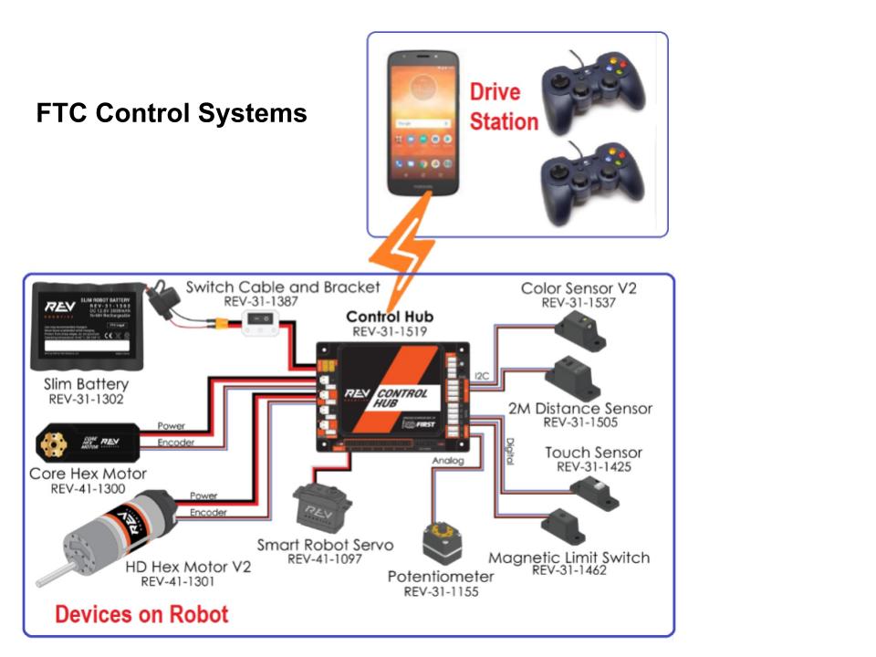 Figure 1: FTC Hardwares (Control Systems)
Before starting FTC programming, it is necessary to understand what hardware the code is interacting with. As shown in Figure 1, the FTC control system consists of two subsystems: the Control Hub and the Driver Station.
Control Hub
The REV Robotics Control Hub is placed on the robot. It has two functionalities:
- The Control Hub has many ports that can connect to different motors, servos, and sensors.
- It also serves as a robot controller. The Robot Controller app, an Android app, runs on the Control Hub. The controller app reads signals from various sensors and sets power or speed to the motors and servos.
Driver Station
The driver station, a separate Android phone, physically connects to gamepads and wirelessly connects to the Control Hub. Through the wireless connection, the Driver Station sends gamepad commands to the Control Hub, and receives telemetry information back and displays it on the Driver Station phone screen.
FTC Software
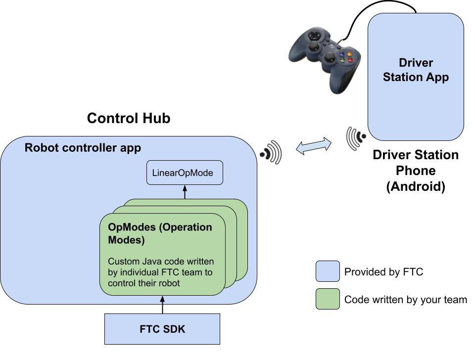 Figure 2: FTC Software Overview
There are two pieces of software used to control an FTC competition robot: the Driver Station App and the Robot Controller App.
Driver Station App
The Driver Station app is an Android app provided by FTC and installed on the Driver Station phone. The human player interacts with the robot through the Driver Station app. The app is available from the Google Play store. No change is needed to the Driver Station app.
Robot Controller App
The Robot Controller app is an Android app that is also provided by FTC and can be downloaded and built from the FTC SDK hosted on GitHub. Changes to the Robot Controller app are necessary to add team-specific control logic by implementing OpMode classes.
OpMode is short for Operational Mode. An OpMode is a class inheriting from LinearOpMode to implement the control logic for one control strategy used either in the 30-second autonomous or in the 2-minute manual driving duration. A team can develop as many OpModes as needed to apply different strategies to handle different situations a team might face during the competition time.
An OpMode performs these three basic operations:
- Read inputs from various devices connected or gamepad
- Do some type of computation based on the inputs
- Send commands to motors and servos to move the robot or other subsystems
There are two different OpModes used during the course of the two and a half minute competition.
Autonomous Mode
The robot operates by itself through the preprogrammed commands (30 seconds). In this mode, the control logic is fully automatic. Code example for this mode:
// @Autonomous annotation indicates this OpMode will run in the autonomous mode
@Autonomous(name = "Example Autonomous Linear OpMode", group = "Leaner Opmode")
// @Disabled: this is to disable or enable the opmode
public class AutonomousOpMode extends LinearOpMode {

    @Override
    public void runOpMode() throws InterruptedException {
        // Initialization code goes here.

        // Gets the all four motors
        DcMotor leftFrontDrive  = hardwareMap.get(DcMotor.class, "leftFront");
        DcMotor leftRearDrive   = hardwareMap.get(DcMotor.class, "leftRear");
        DcMotor rightFrontDrive = hardwareMap.get(DcMotor.class, "rightFront");
        DcMotor rightRearDrive  = hardwareMap.get(DcMotor.class, "rightRear");

        // Most robots need the motor on one side to be reversed to drive forward
        leftFrontDrive.setDirection(DcMotor.Direction.FORWARD);
        leftRearDrive.setDirection(DcMotor.Direction.FORWARD);
        rightFrontDrive.setDirection(DcMotor.Direction.REVERSE);
        rightRearDrive.setDirection(DcMotor.Direction.REVERSE);

        // Wait for the game to start (driver presses PLAY)
        waitForStart();

        // The autonomous program will drive the robot forward for 2 seconds with
        // power set to 0.5 and then stop.
        ElapsedTime runtime = new ElapsedTime();
        runtime.reset();
        while (opModeIsActive()) {
            if (runtime.time() < 2.0) {
                leftFrontDrive.setPower(0.5);
                leftRearDrive.setPower(0.5);
                rightFrontDrive.setPower(0.5);
                rightRearDrive.setPower(0.5);
            } else {
                break;
            }
        }
    }
}
TeleOp Mode
The robot is manually controlled through the inputs from the gamepad (2 minutes). The code may incorporate autonomous aided control logic to enhance the robot’s performance and efficiency. Code example for this mode:
// @TeleOp annotation indicates this OpMode will run in the TeleOp mode
@TeleOp(name = "Example Tele Linear OpMode", group = "Linear Opmode")
// @Disabled: this is to disable or enable the opmode
public class ExampleTeleop extends LinearOpMode {

    @Override
    public void runOpMode() {
        // Initialization code goes here.

        // Gets the all four motors
        DcMotor leftFrontDrive  = hardwareMap.get(DcMotor.class, "leftFront");
        DcMotor leftRearDrive   = hardwareMap.get(DcMotor.class, "leftRear");
        DcMotor rightFrontDrive = hardwareMap.get(DcMotor.class, "rightFront");
        DcMotor rightRearDrive  = hardwareMap.get(DcMotor.class, "rightRear");

        // Most robots need the motor on one side to be reversed to drive forward
        leftFrontDrive.setDirection(DcMotor.Direction.FORWARD);
        leftRearDrive.setDirection(DcMotor.Direction.FORWARD);
        rightFrontDrive.setDirection(DcMotor.Direction.REVERSE);
        rightRearDrive.setDirection(DcMotor.Direction.REVERSE);

        // Wait for the game to start (driver presses PLAY)
        waitForStart();

        // run until driver presses STOP button
        while (opModeIsActive()) {
            // Drive the robot forward or backward based on the left joystick's
            // y value
            double drive = gamepad1.left_stick_y;
            leftFrontDrive.setPower(drive);
            leftRearDrive.setPower(drive);
            rightFrontDrive.setPower(drive);
            rightRearDrive.setPower(drive);
        }
    }
}
Software Environment Setup
Step 1: Download and Install Android Studio
As mentioned in the introduction section, an FTC software program is actually an Android app running on the Android operating system. Android Studio is an Integrated Development Environment (IDE) used for developing Android apps. Download Android Studio and install it on your computer.
Note: Java is the programming language for Android and it will be installed as part of the Android installation package.
Step 2: Set Up FTC SDK
The FTC SDK has many useful built-in libraries used for interacting with various devices such as commonly used motors, servos and sensors. Most importantly, it contains the robot controller main app together with the OpMode programs that you are going to write to control the robot.
- Import the FTC SDK into Android Studio by following these steps:
-
Go to Android Studio and click “Clone Repository”

-
Paste in the link of the official FTC SDK:
https://github.com/FIRST-Tech-Challenge/FtcRobotController/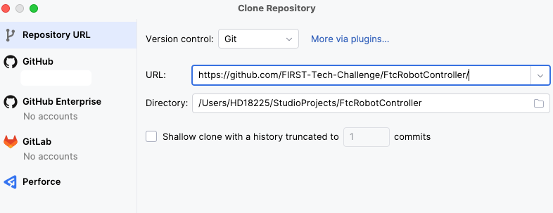
-
Click on the “Clone” button
-
Note: more info about using the FTC SDK can be found on the FTC SDK readme page.
Step 3: Connect to the Control Hub
- Power on the control hub by plugging in a battery and wait for ~5 seconds until the hub light turns green
- On your computer, click on the WIFI selector to switch the WIFI to the control hub WIFI with a name something like ‘FTC-xxx’ and the default password is ‘password’. You could change the WIFI network name and password by opening this page in a browser:
192.168.43.1:8080 - Deploy code wirelessly by running this adb command:
adb connect 192.168.43.1:5555in the terminal (either the Android Studio terminal or your computer’s built-in one)
Note: more details about using the control hub can be found here.
Step 4: Set Up Driver Station Phone
- Install the FTC Driver Station app on an Android (Driver Station) phone from the Play Store
- Alternatively directly install the code by going to the GitHub releases page and clicking on “Source code (zip)” link to download.
- Connect the Driver Station phone to the Control Hub by following this guide
- Configure the robot in the Driver Station app by following this tutorial
Programming in Android Studio
- Once the FTC SDK is imported into Android Studio, you should see a TeamCode folder in the project tree. When writing new OpModes, the ‘TeamCode’ folder is where the new code will be stored
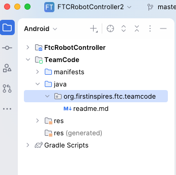
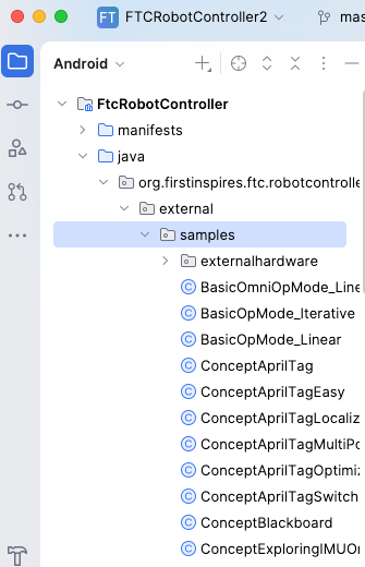
- To start, you can copy any existing example OpMode from the ‘external.sample’ folder under the ‘FtcRobotController’ folder and then make changes on top of it
- A typical OpMode class has the following code structure. The custom code for robot control logic will be added to the initialization section and the three sections inside the WHILE loop.
@Autonomous(name = "Example Autonomous Linear OpMode", group = "Leaner Opmode")
// @Disabled: this is to disable or enable the opmode
public class AutonomousOpMode extends LinearOpMode {

    @Override
    public void runOpMode() throws InterruptedException {
        // Initializing motors, sensors and servos
        // Your initialization code goes here

        // Wait for the game to start (driver presses PLAY)
        waitForStart();

        // Any code that needs to perform once after pressing START goes here

        while (opModeIsActive()) {
            // get inputs from sensors or gamepad

            // do some computation

            // set output to motors and servos
        }
    }
}
To program with various hardwares, continue to the next section. More details for Android programming can be found on the FTC resource page: Comprehensive Android Programming Guide.
Programming with Hardwares
An OpMode is either a LinearOpMode or an Iterative OpMode (for more details see Appendix A). For either case, the base class contains a HardwareMap and two GamePad objects. The HardwareMap is the object from which you can get the handles for all other devices based on the device type and device name you set in the robot configuration.
Motors
Motors in FTC are used when you need a mechanism which rotates 360 degrees either continuously or on command. A well known use case is the drive base. In this guide, we use the Andymark NeveRest Classic 40 GearMotor as an example. This motor equips an onboard encoder which helps in calculating the number of ticks (robot language for inches) the robot traveled.
- Get the motor object from the HardwareMap
DcMotor leftFrontDrive = hardwareMap.get(DcMotor.class, "leftFront");
Notes:
- ‘hardwareMap’ is a member variable defined in the base class LinearOpMode which is provided by the FTC SDK
- The used motor is a DcMotor. Hence, the first parameter (device type) is
DcMotor.class - “leftFront” is the name we used to name the left front motor in the robot configuration. This name is configurable. See this guide for more info on how to configure the robot.
- Initialize the motor properly
leftFrontDrive.setDirection(DcMotor.Direction.FORWARD);
Notes:
- This statement determines if the motor will rotate forward or backward when setting a positive power. Setting the direction to
DcMotor.Direction.REVERSEis necessary for motors installed on the opposite side of the robot
- Set a power to the motor to start moving the robot
leftFrontDrive.setPower(0.5);
Notes:
- The range for power is [-1, 1]. A positive value makes the motor rotate in the direction that moves the robot forward, and a negative value makes the motor rotate in the direction that moves the robot backward.
Servos
The main difference between servos and motors is that servos can only rotate within a limited angle range less than 360 degrees such as 180 degrees and 270 degrees. Hence, a servo can’t be rotated continuously. In this guide, we assume the servo has the angle range 0-180 degrees.
- Get the servo object from the HardwareMap
Servo armSlider = hardwareMap.get(Servo.class, "armSlider");
Notes:
- ‘hardwareMap’ is a member variable defined in the base class LinearOpMode which is provided by the FTC SDK
- The used servo is a Servo. Hence, the first parameter (device type) is
Servo.class - “armSlider” is the name we used to name the servo in the robot configuration. This name is configurable. See this guide for more info on how to configure the robot.
- Initialize the servo so that the initial angular position is at 0 degrees
armSlider.setPosition(0);
- Rotate the servo to the 90 degree angle
armSlider.setPosition(0.5);
Sensors
A common sensor used in FTC is the color sensor. The color sensor is useful when you want to rely on color to navigate the robot. For example, the example code below shows you how to stop the robot when it sees the red color.
- Get the motors and color sensor object from the HardwareMap
DcMotor leftWheel  = hardwareMap.get(DcMotor.class, "leftWheel");
DcMotor rightWheel = hardwareMap.get(DcMotor.class, "rightWheel");
NormalizedColorSensor colorSensor = hardwareMap.get(NormalizedColorSensor.class, "sensor_color");
Notes:
- Any color sensor can be returned as a
NormalizedColorSensor.
- Initialize the motors by setting the right direction
leftWheel.setDirection(DcMotor.Direction.FORWARD);
rightWheel.setDirection(DcMotor.Direction.REVERSE);
- Move the robot until it senses the red color
if (colorSensor.getNormalizedColors().red > 0.9 &&
    colorSensor.getNormalizedColors().green < 0.1 &&
    colorSensor.getNormalizedColors().blue < 0.1) {
  leftWheel.setPower(0.0);
  rightWheel.setPower(0.0);
} else {
  leftWheel.setPower(1.0);
  rightWheel.setPower(1.0);
}
Gamepads
There are two predefined Gamepad objects in the LinearOpMode base class: gamepad1 and gamepad2. In this guide, we will demonstrate how to move the left motor when pushing the left stick forward on gamepad1, and how to move the right motor when pushing the right stick forward on the same gamepad.
- Get the motor objects from the HardwareMap
DcMotor leftWheel  = hardwareMap.get(DcMotor.class, "leftWheel");
DcMotor rightWheel = hardwareMap.get(DcMotor.class, "rightWheel");
- Set the motor direction
leftWheel.setDirection(DcMotor.Direction.FORWARD);
rightWheel.setDirection(DcMotor.Direction.REVERSE);
- Move the motors based on the joystick’s inputs on gamepad1
leftWheel.setPower(-gamepad1.left_stick_y);
rightWheel.setPower(-gamepad1.right_stick_y);
Notes:
- When pushing the joystick forward, both joysticks (
left_stick_yandright_stick_y) return a negative value. To move the motor forward, we need to negate the value here.
Additional Resources
- Game Manual Zero Software Guide (Highly Recommended)
- Comprehensive Android Programming Guide
- FTC SDK Javadoc references
- Various FTC programming video tutorials
- FTC programming resources
Source Code Version Control
Overview
- A version control system allows everybody on the team to work on any file at any time they want. Without it, it would be very difficult to manage having multiple people working on the same document.
- How it works is that you have a master repository, and every member copies that onto their own computer. Once a member is done editing, they upload the changes (push) onto the master repository, and the rest of the team will download those changes (pull).
- A version control system will keep track of all the changes, which makes it very handy as a backup in case something goes wrong, or if you need to reference it for later.
- For this example, we will be using GitHub because it is used by almost everyone in the FTC community and is also widely used throughout the world, although there are still alternatives.
Ways to Interact with GitHub
- Git command line tools
- GitHub desktop app
- Android Studio built-in tools
Set Up a Team GitHub Repository
- Create a GitHub team account and sign in
- Go to the latest version of the FTC Robot Controller on GitHub
- Click on the ‘Fork’ button on the top right corner
- This will be the team database that everybody pushes/pulls from
Note: for more details, refer to this guide on managing the repository.
Appendix
Appendix A: Linear OpMode vs Iterative OpMode
Programming a robot is primarily based on loops, in which your robot repeatedly calls code, such as operating a motor or getting input from a sensor. So, the two types of OpModes, Iterative and Linear, are both based around looping. For an Iterative OpMode, the “loop()” method defined in the class “OpMode” will be repeatedly executed when play is pressed all the way until stop is pressed. For a Linear OpMode, the code in the “runOpMode()” method will only be executed once when play is pressed, and looping isn’t built in.
Appendix B: Clone FTC SDK to your local disk
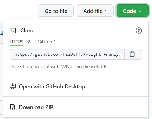
- Click the green button that says “Code,” and copy the URL of the team GitHub repository
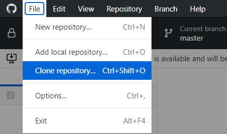
- If using the GitHub desktop app, open GitHub Desktop, click “File”, and then “Clone Repository”
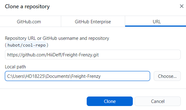
- Click “URL,” paste the URL that you just copied, choose the file location that you want it to be downloaded to, and click “Clone.”
Appendix C: Example FTC project on GitHub
This GitHub repository contains examples of TeleOp and Autonomous OpModes used for driving a simple robot based on the FTC SDK for Freight Frenzy (2021-2022 competition season).
Link to the example code: https://github.com/HiiDeff/Duck
Conclusion
We hope that this guide helped you in the basics of FIRST Tech Challenge programming and wish you the best in your journey forward. High Definition is always happy to mentor your team! Feel free to email us at ftc18225@gmail.com.
Originally written by Allen Wu and Rishabh Venkatesan. Edited by Andrew Chen